Let’s get physical
Thursday 6 May 2021
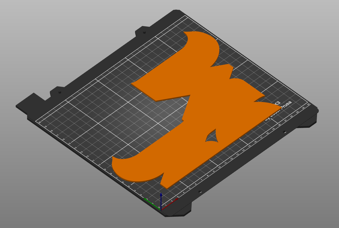
3D
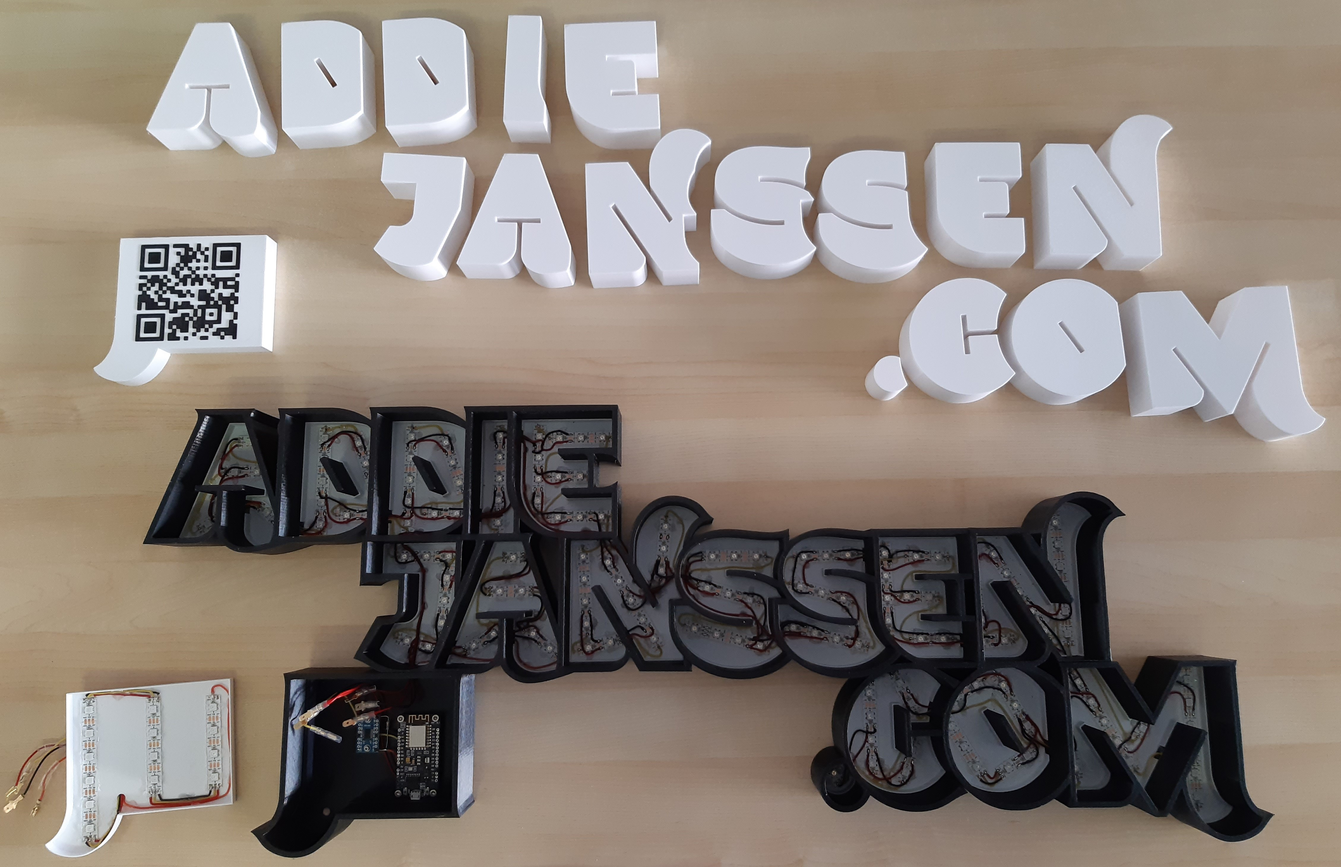
It took over 165 hours to print all the parts of the name sign. By now I have:
- 5 parts that make up the backside of the name sign
- 5 parts that make up the casing of the characters
- 16 parts that make up the fronts of all the characters
- 5 parts that make up the QR/electronics box.
And I have 171 LEDs that need to get in there and need to be connected to the microcontroller.
Time to assemble the name sign.
To glue or not to glue?
The initial plan was to glue all the backside parts together to make one solid part and do the same thing with the casing parts. But when I pushed some of the casing parts on top of the backsides, I noticed that it takes a lot of force to separate them again. Due to their form, there is a lot of friction between the parts which is good, since it will make sure that the sign will not fall apart. However, if I would glue them all together, I wonder if I can assemble the whole sign.
I decided to take another approach: I will glue the backsides together but will not do so with the casing parts. The backside needs to become a single part anyway, since I will need to run all the cables between the LEDs in there.
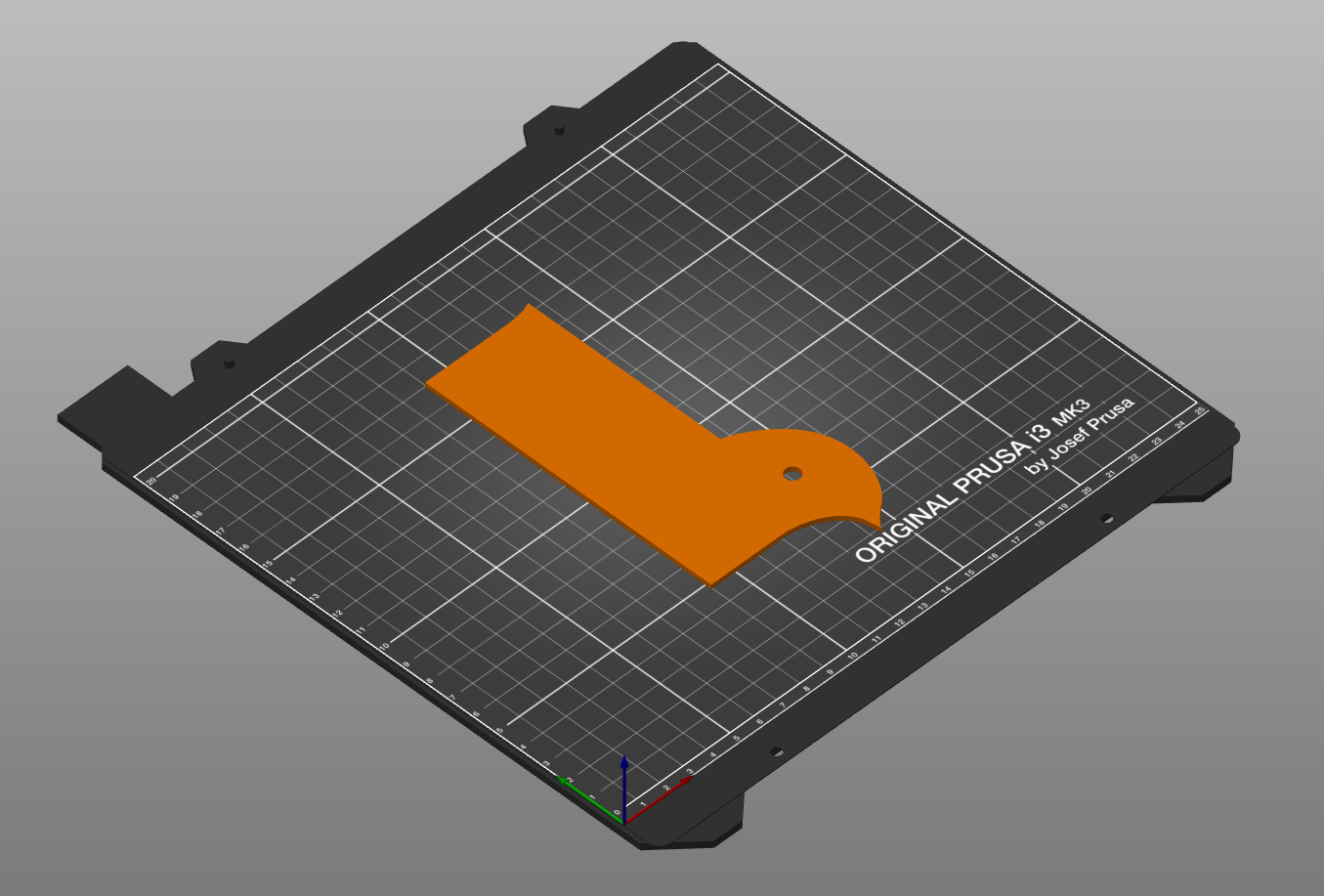
Gluing the 5 parts that make up the backside is going to be tricky. The backside is only 2 mm thick and there is not a lot of surface where the parts contact each other. I should have thought about this during design time of course, but hey: this is a learning project…
Choosing the right type of glue will be critical. So, I went out and bought a few types of glue and then tested them on small 2 mm thick pieces that I printed. Left all of them to set over night and then next day tried to break them. Some of them snapped immediately, but I got one that I could hardly break. Those were glued using Pattex Super Gel and that is glue I used for the backside.
It was a bit scary since it took forever to print these parts, but it had to be done. And here’s the result:
I left it to dry for 24 hours and then it was time to pick it up. Would it break? Well, it didn’t. But it was pretty “flexible”. I was not happy with the strength, but for now, it is good enough.
Electronics
While I was waiting for the glue to dry, I assembled the electronics box. I then realized that I made a small mistake: I planned to use M2 screws for all the parts, but apparently, I printed M3 mounts for the microcontroller. Not a big problem, but yet another small issue I missed during design time.
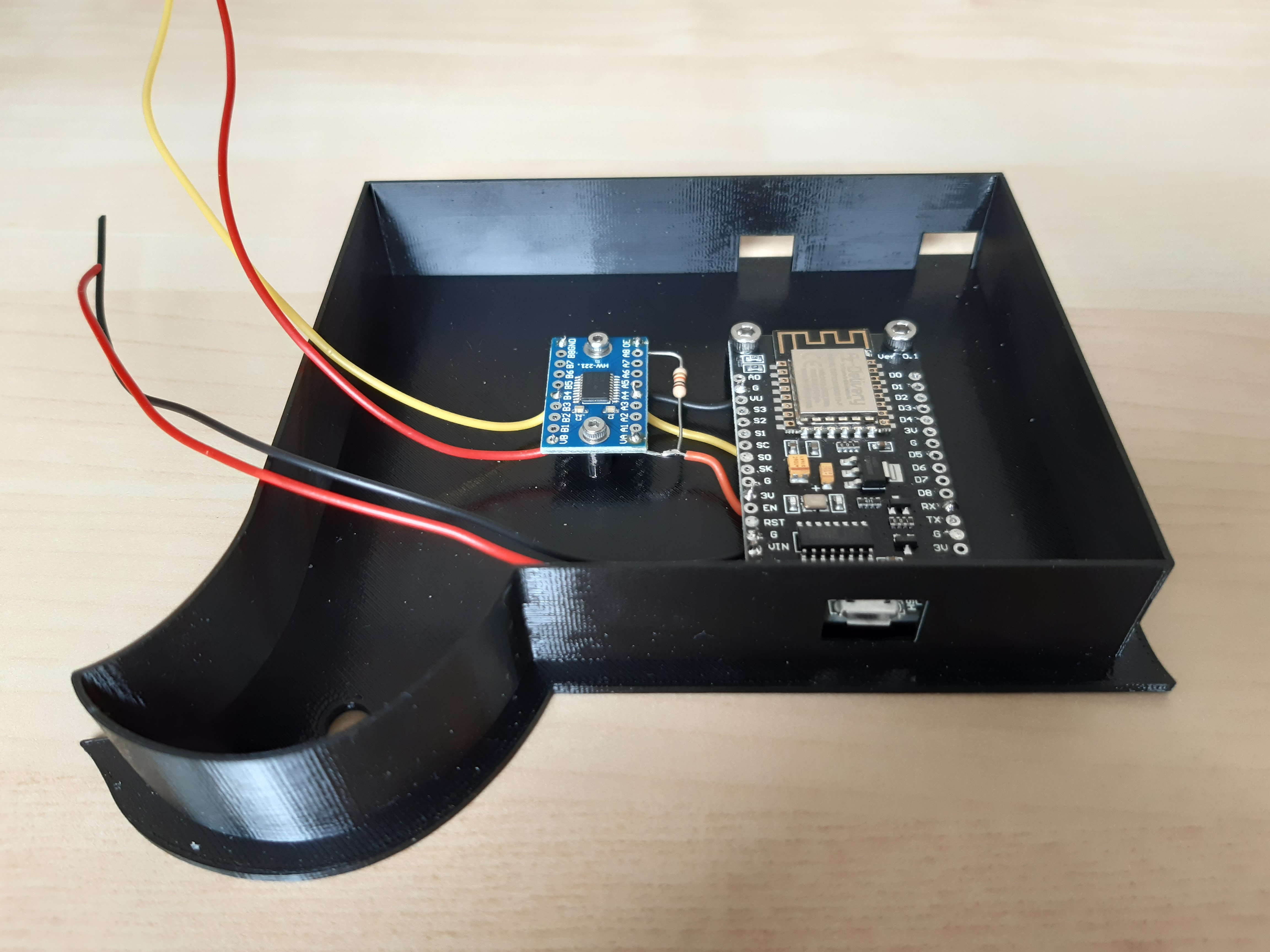
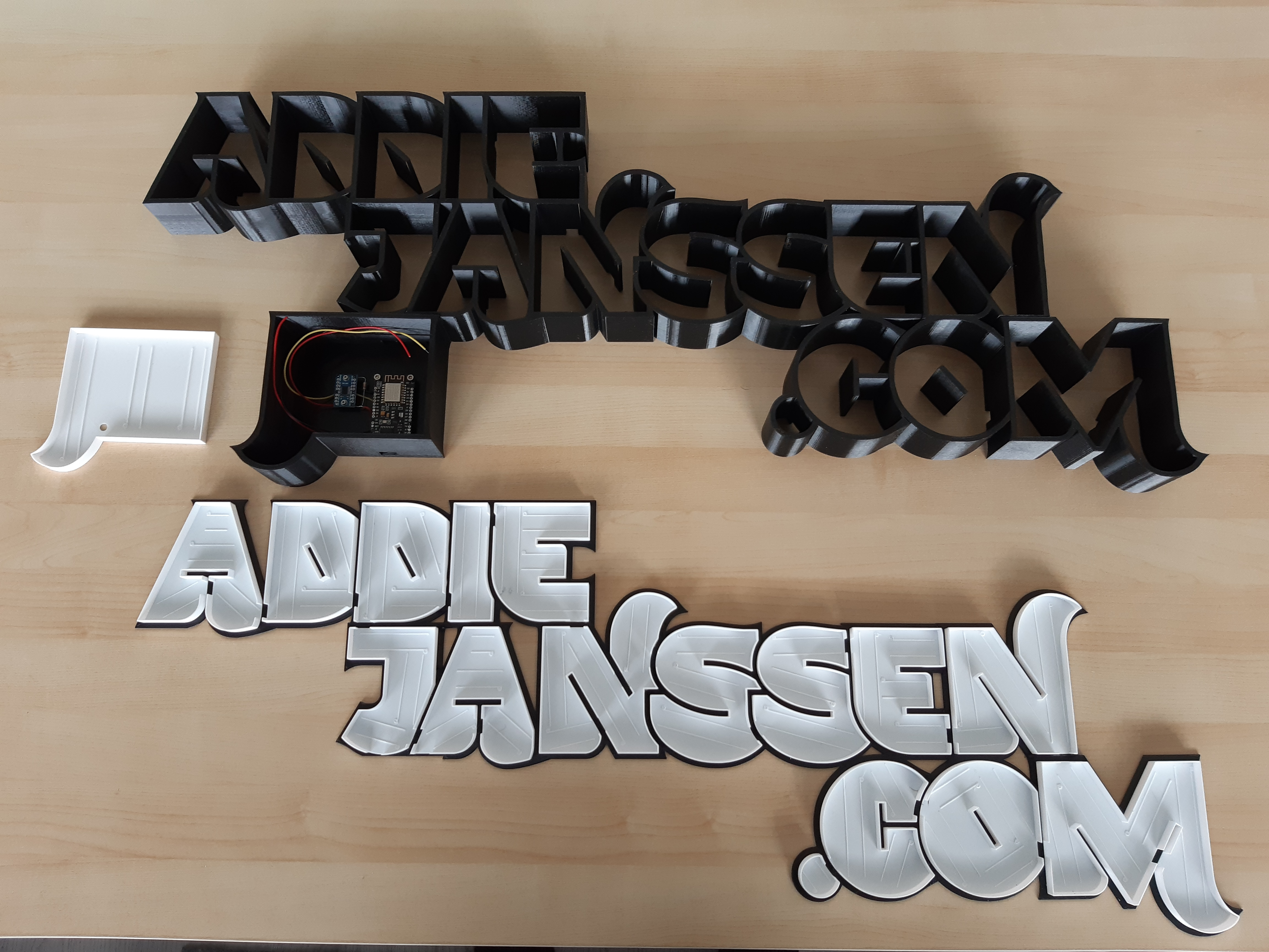
So, now I have the backside, the casing, and the electronics box.
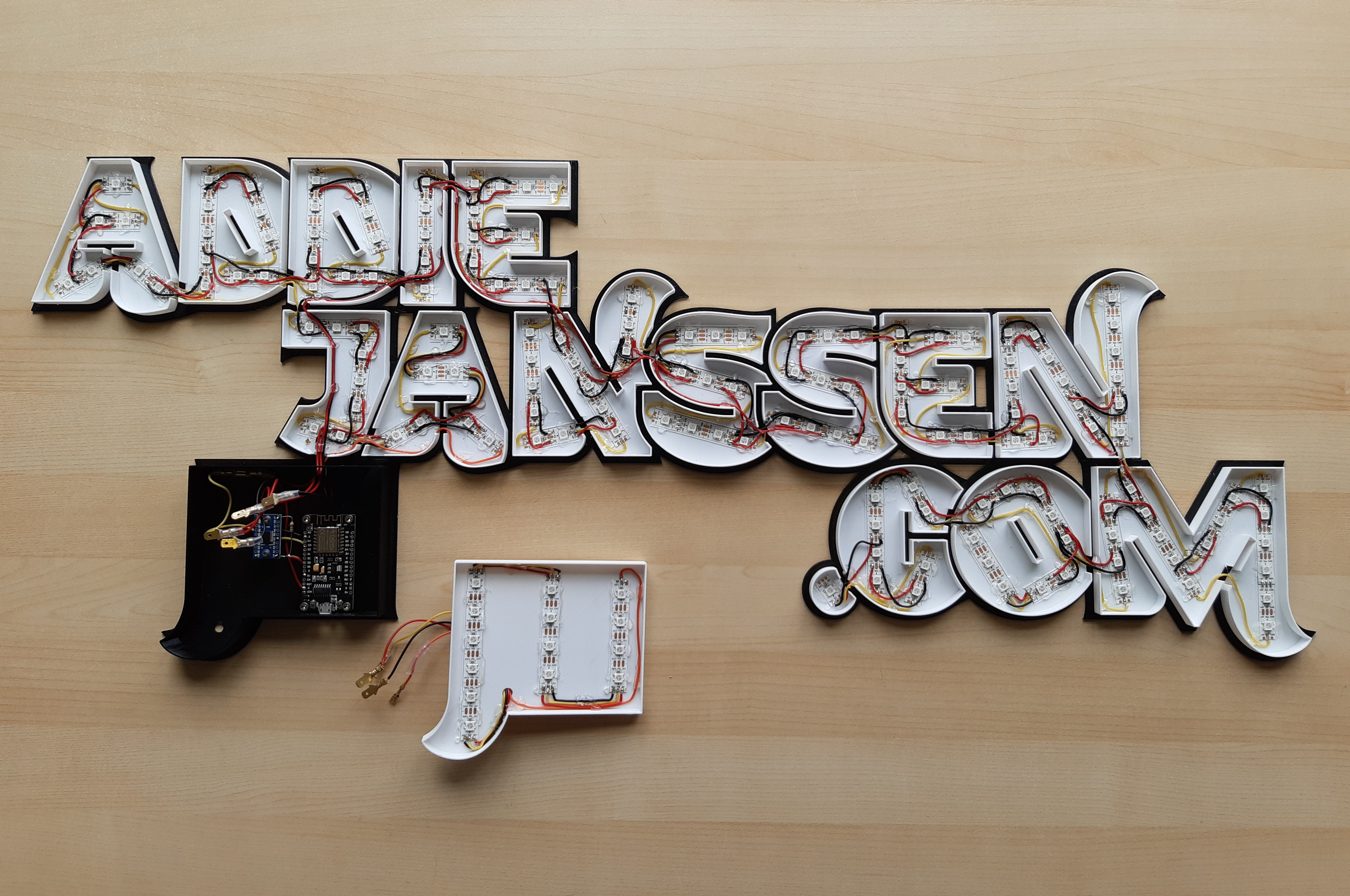
LEDs and lots of them
Next step in the assembly process was to glue the LED strips onto the backside and solder wires to connect them. It took me 2 full days to get them all in. Along the way, I tested them to make sure that I would not end up with a few broken LEDs.
There are 171 LEDs in the name sign and when they are all at full power, they will drain 8.5 A. Each little cable will introduce a little bit of resistance and that will result in power loss. So, I measured the voltage at the first connection and then over the last LED and noticed 1.5 V difference. That is too much. I fixed it, by running a second cable to the first “S” character and inject power roughly half-way in the sign. The result was a drop of only 0.5 V at full power; good enough.
I used a hot glue gun to glue all the cables and LEDs; I didn’t want them to come loose after some time.
Does it fit?
By now, I have all the components. Time to stick the casing parts on the backside and add the fronts.
That is a tight fit. I will have a hard time to take that apart if something needs fixing. The whole thing fits and stands, but it is very flexible…
Strengthen the backside
To strengthen the backside, I came up with a simple solution: just print another 2 mm thick layer and glue that to the back. I used straight lines to cut up that layer into 6 sections and made sure that the parts would overlap the lines where the backside parts were initially glued together. The OpenSCAD files have been published on my GitHub account for reference.

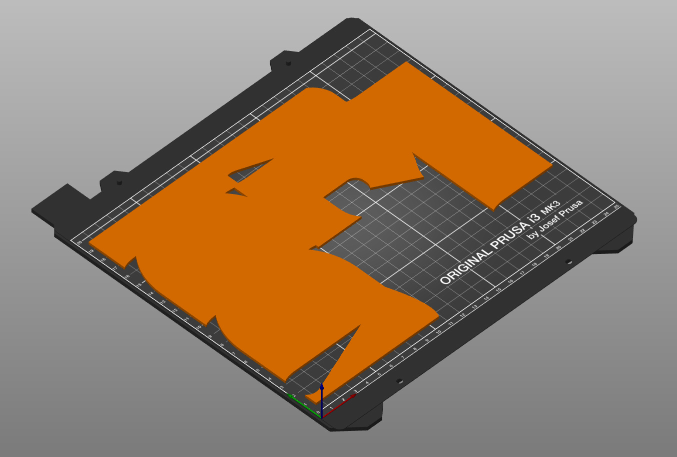
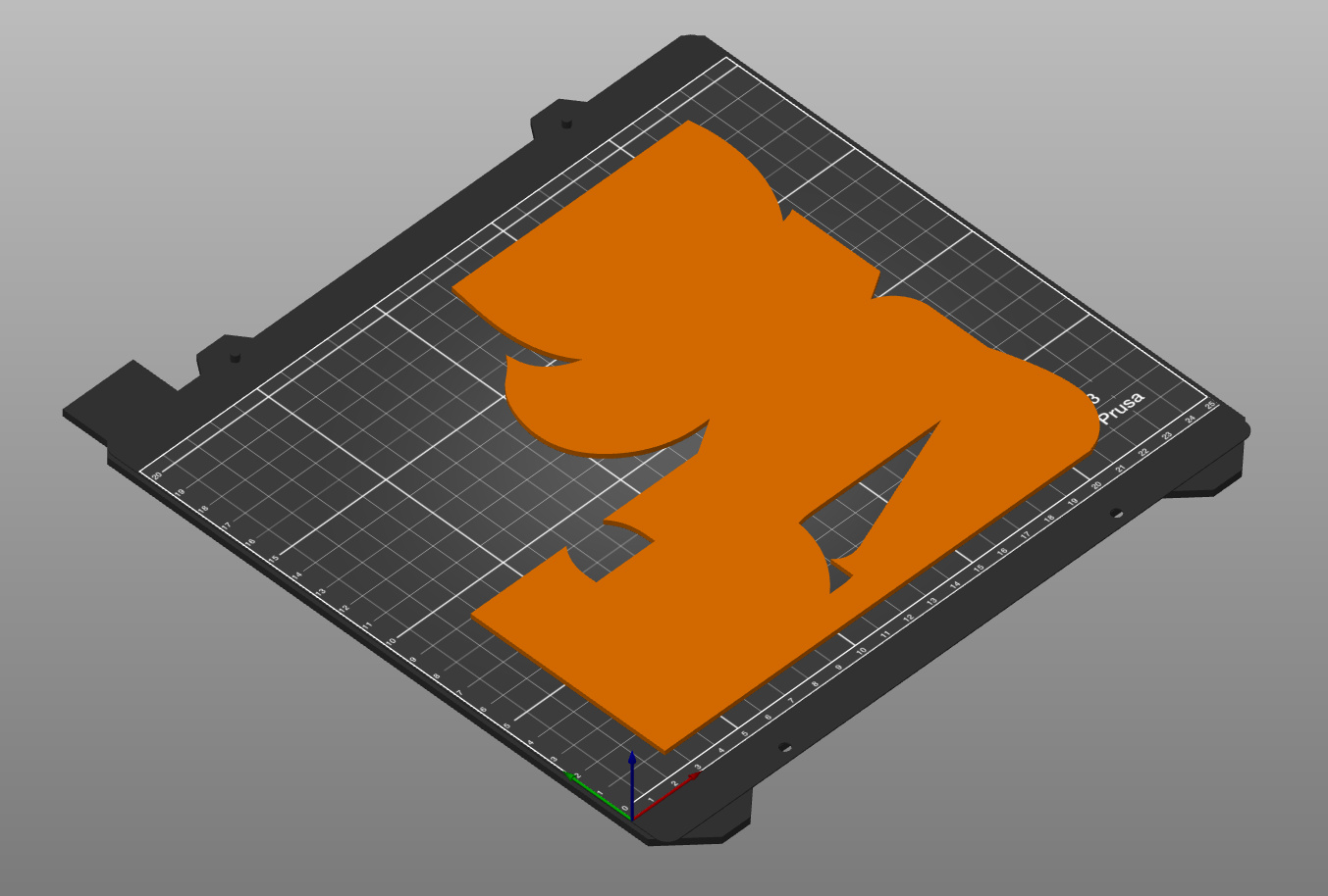

I then used a regular contact glue to glue those parts to the back of the sign. That made the whole thing much stiffer.
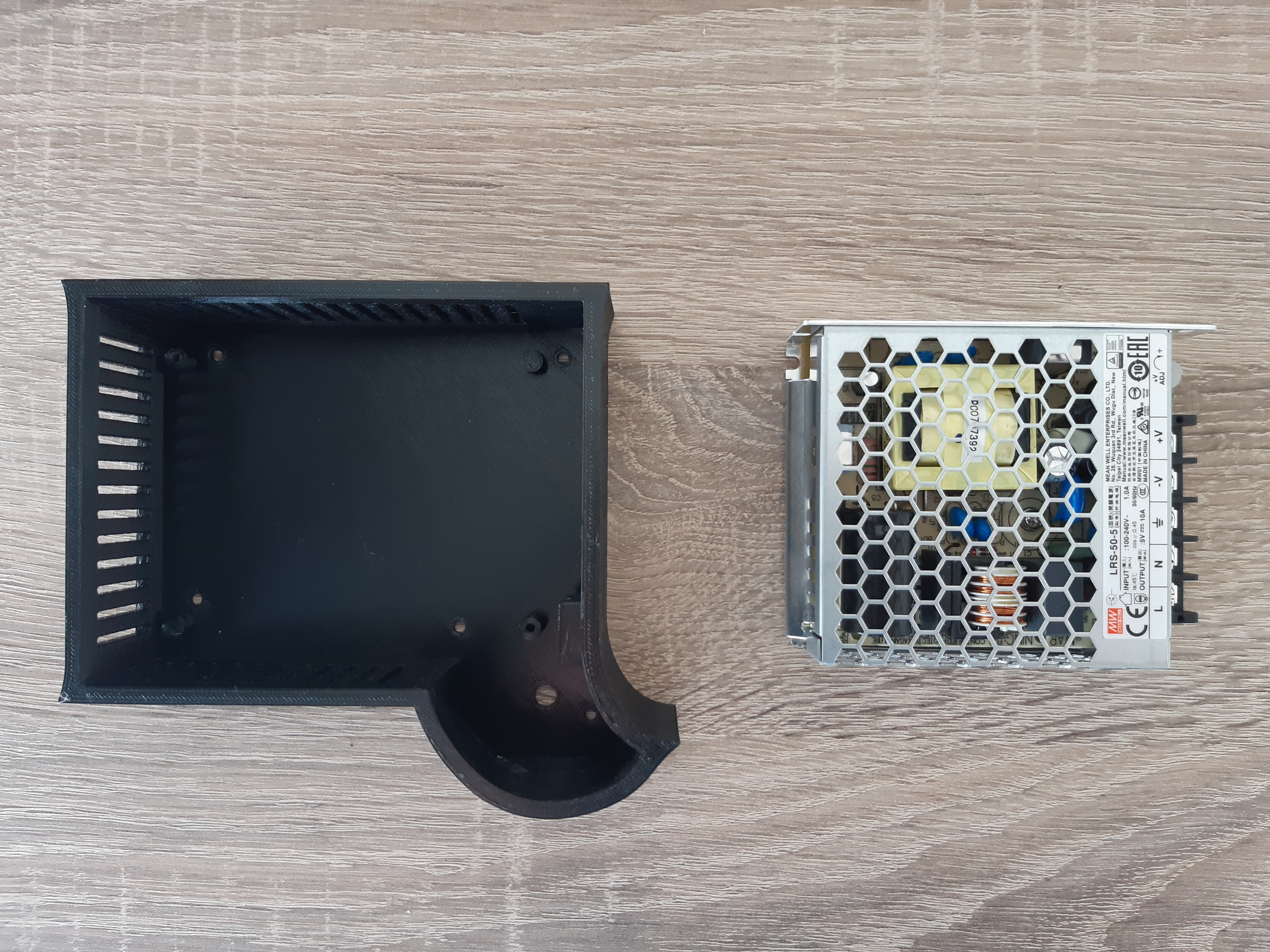
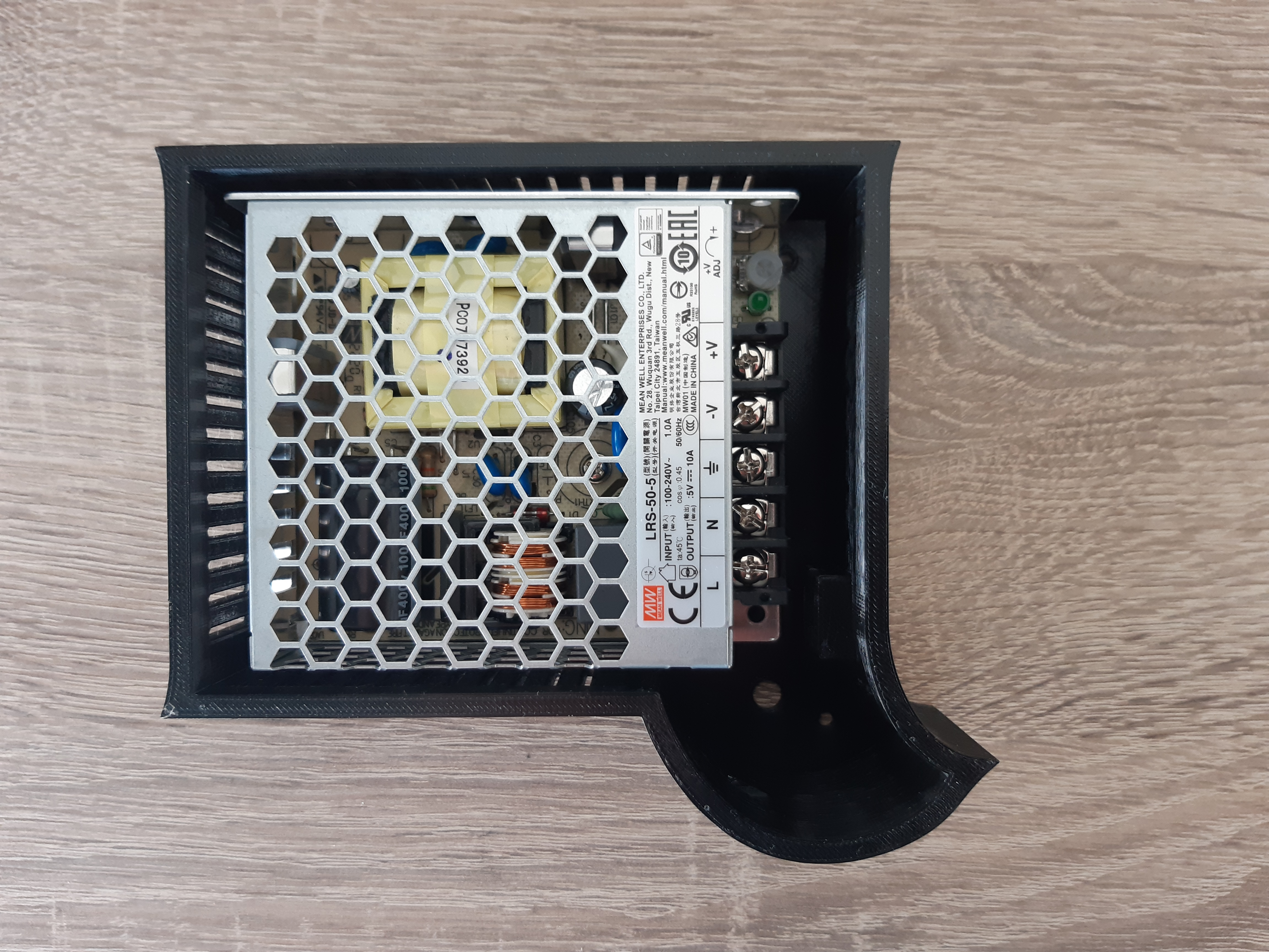
Power supply
The initial idea was to use an external power supply; something similar as used by laptops. But I could only find one that would deliver enough power at 5V and it was costly. I then decided to look at the switching power supplies of Mean Well. That vender has so many different types, there must be one that does what I need. And yes, there it was: LRS-50-5. It can deliver up to 50 Watt at 5V and it is dirt cheap.
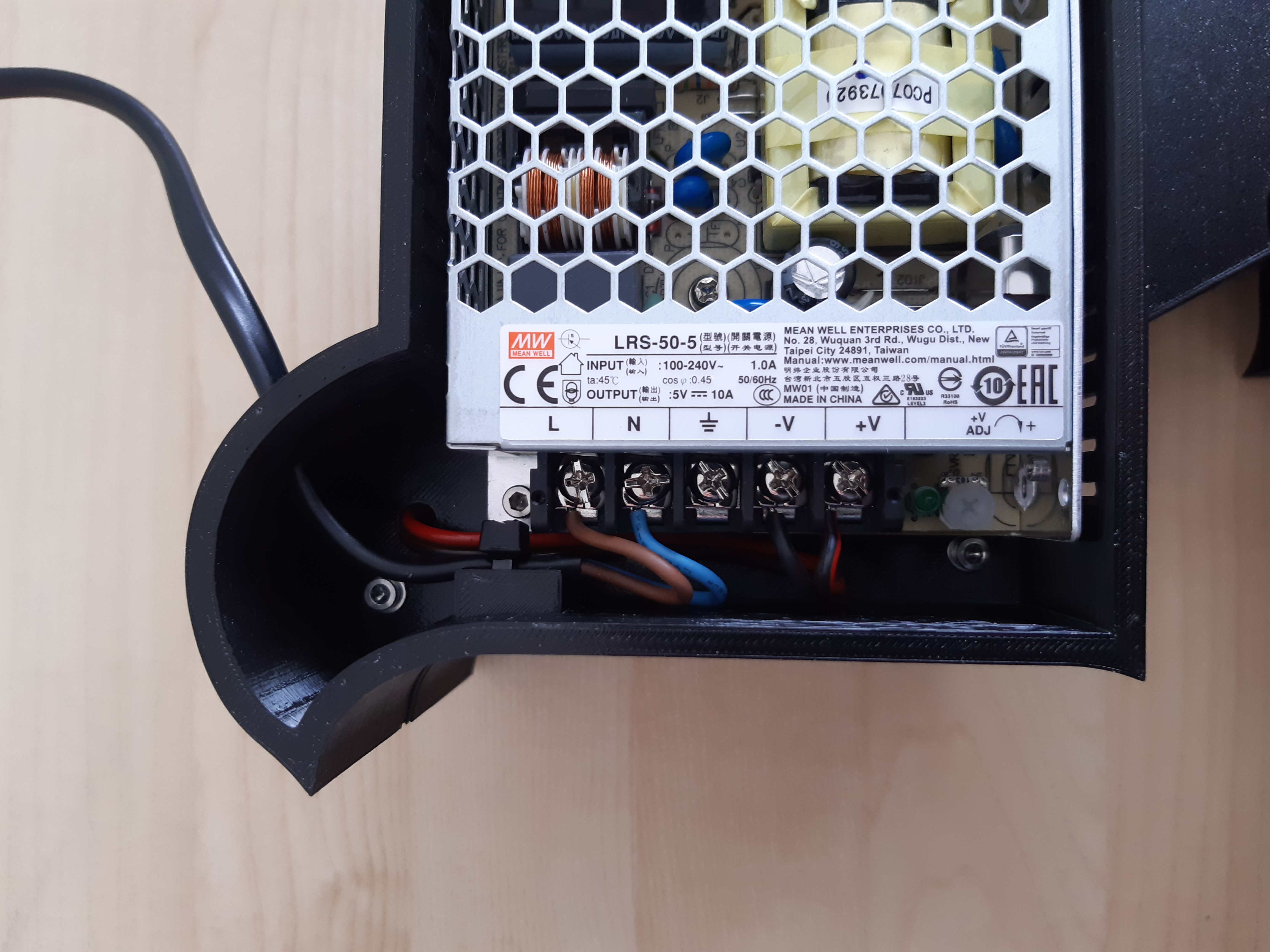
This power supply needs a case; I can’t just drop it onto the table. Luckily, the size of this thing was a perfect match for the QR/electronics box. So, I designed a nice box for the power supply that can be bolted to the back of the QR/electronics box. I added a lot of slots to the (invisible) sides for natural ventilation. And I added a cable clamp for the power cable.
The design has also been added to my GitHub account.
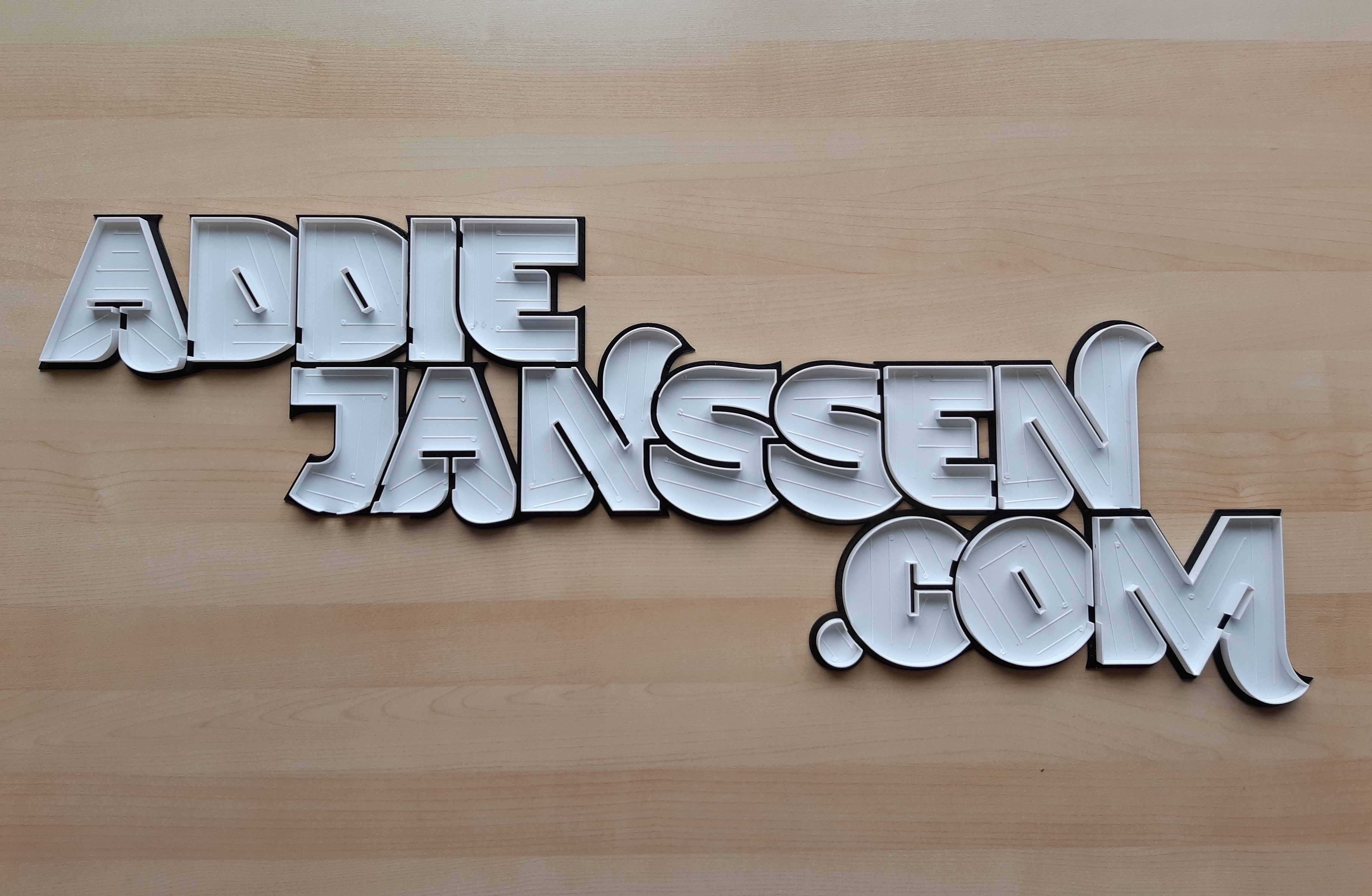
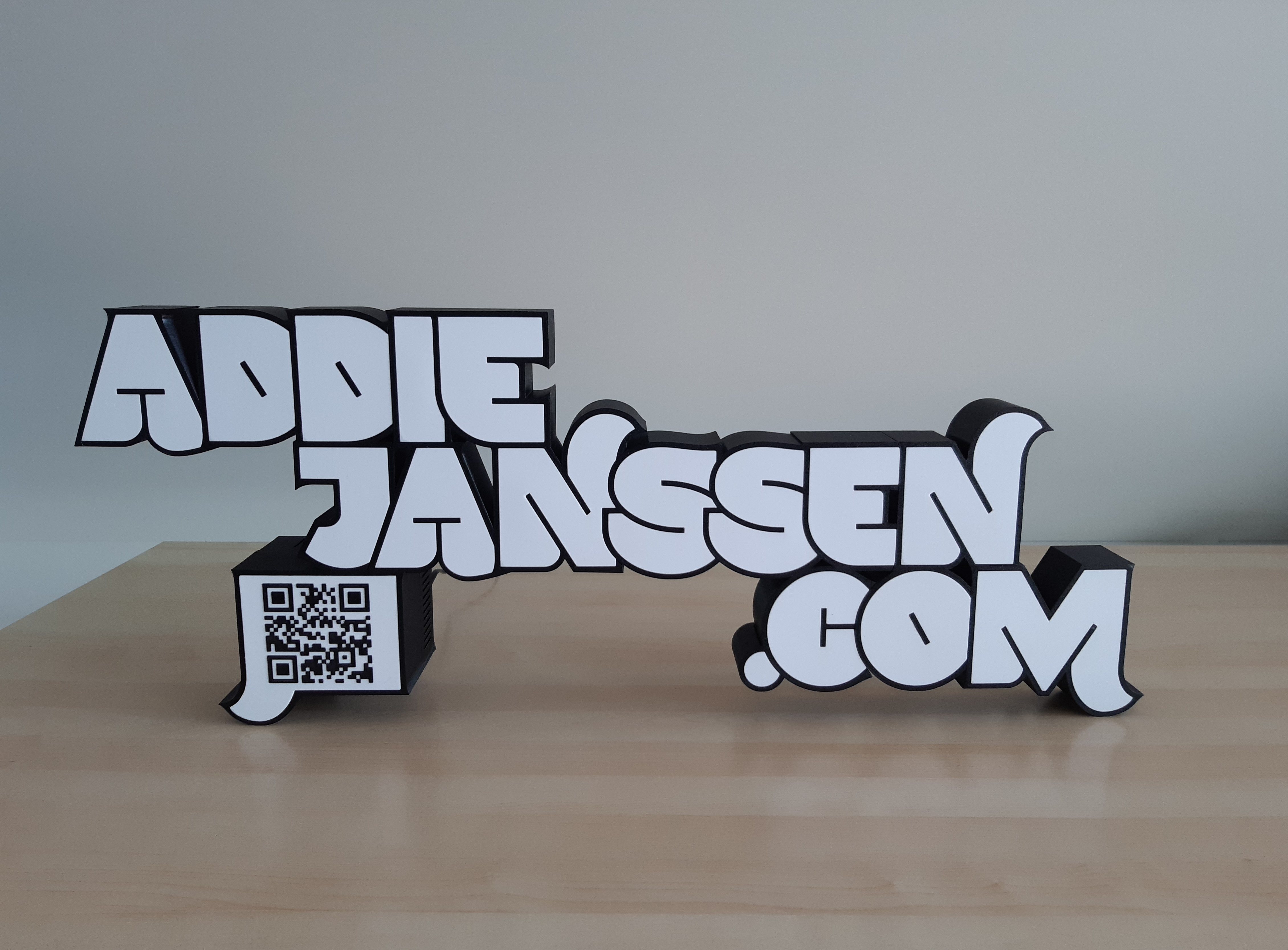
The end result
Done! The name sign is assembled.

Want to respond to this post?
Look me up on Twitter,
 Facebook or
 LinkedIn.
Tags
- 3D 9
- Air Safari 19
- Australia 67
- BlackBerry 1
- Blue Sky Flying Adventures 33
- By Boat 4
- By Bus 2
- Dev Containers 3
- Domoticz 2
- Driving 31
- Facebook 1
- Flying 36
- Gallery 2 7
- Google Maps 4
- Hugo 1
- Jekyll 4
- Linux 3
- NextGEN Gallery 5
- Podman 3
- Red Centre Tour 19
- Singapore 3
- Tasmania 10
- USA 33
- WSL 2 4
- Walking 42
- WordPress 17