Finalizing the design of the name sign
Tuesday 4 May 2021
3D
By now, it is clear how the name sign should look like and we now know how the LEDs behave and how to diffuse the light. And since I did some test prints, I know that the individual parts seem to work. Time to work out all the nitty gritty details of the design and prepare the 3D print files.
The OpenSCAD modules and files
I have published the design on my GitHub account. The name sign is designed using OpenSCAD modules for individual parts of the design:
NameSign.scadis the main design file and is the entry point to render the individual components or parts.Settings.scadholds all the settings of the design.Casing.scaddefines the modules that make up the outline of the name sign. Basically, all the parts that are based on theNamskoutfont. The only exception to this is the electronics box with the QR code; that is done in its own file.Front.scadis used to define all the modules that make up the front parts of the individual characters. This includes all the parts that are based upon theNamskinfont.QRBox.scadholds all the modules that make up the electronics box with the QR code.Back.scaddescribes all the modules that make up the backside of the name sign.
Next to these files, there are a bunch that define specific supporting modules:
LED.scadhas some modules that allow for easy placement of the LEDs on the back side parts.CutOut.scadis used to help making the gaps between the characters where we can run the cables through to connect the LEDs.ESP8266.scadandTXS0108.scaddefine the modules to place the microcontroller and level shifter in the QR box.
Let’s have a look at some of the details.
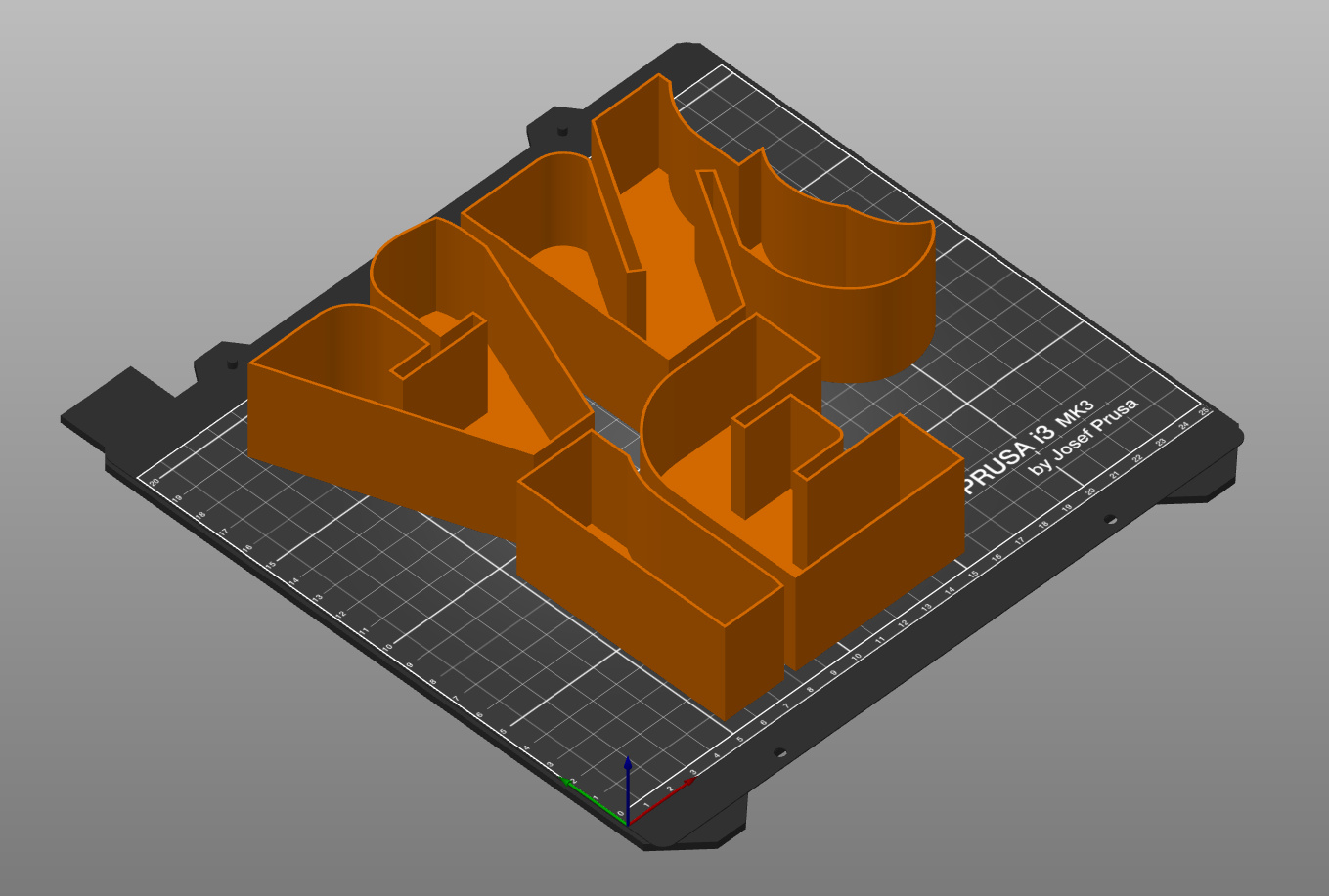
Overlapping the characters
As you probably have seen in another post, the name sign is split up in 3 lines of characters.
The Settings.scad file holds a whole set of variables defining which characters are on which line and where they should be in the line.
Now, the characters are not just pushed against each other; they overlap. This is how this is handled in the design:
module Casing2D()
{
    for (l = [0 : LineCount]) {
        translate ([LineXSpace[l] - XSpace[LineStart[l]], LineYSpace[l],0])
            for (i = [LineStart[l] : LineEnd[l] - 1]) {
                if (i < LineEnd[l] - 1)
                {
                    difference() {
                        // -----
                        // Take a character on this line
                        translate ([XSpace[i],0,0])
                            text(Text[i], CaseHeight, font=OuterFontName, valign="baseline");

                        // and then remove the overlapping part of the next character
                        // -----
                        translate ([XSpace[i + 1],0,0])
                            union() {
                                // -----
                                // Make sure that we use the outline and
                                //  the inner part of the character
                                // -----
                                text(Text[i + 1], CaseHeight, font=OuterFontName, valign="baseline");
                                offset(r=0.01)
                                    text(Text[i + 1], CaseHeight, font=InnerFontName, valign="baseline");
                            }
                    }
                }
                else
                {
                    // -----
                    // There is no overlap for the last character in the line
                    // -----
                    translate ([XSpace[i],0,0])
                        text(Text[i], CaseHeight, font=OuterFontName, valign="baseline");
                }
            }
    }
}
The module generates each individual line. For each character, it will “cut out” the part of the next character unless it is the last one on the line.
This is a recurring topic for the casing, the front, and the back. The example shows the module for the casing, but the others are similar.
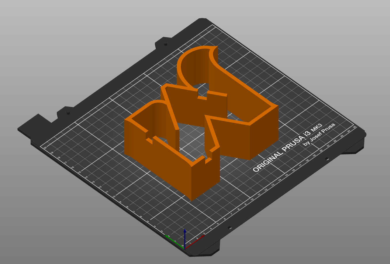
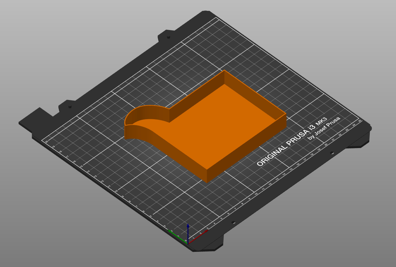
“Connecting” the parts
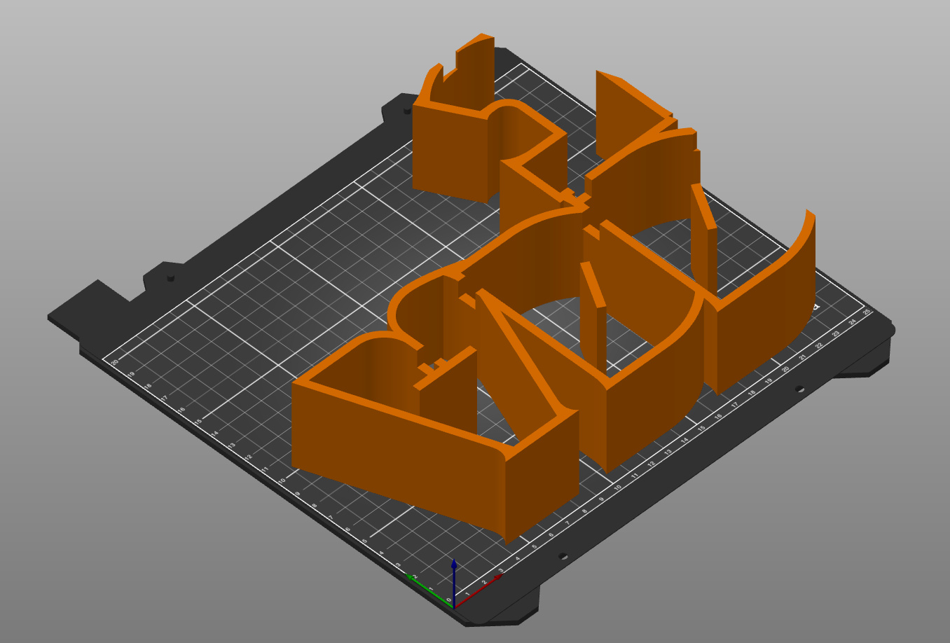
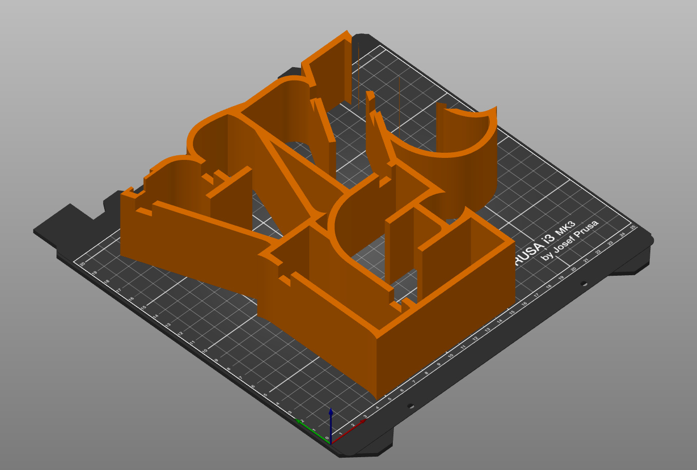
The fronts of the characters nicely fit into the casing due to the 2 different fonts. To get the best quality of light, the side of the fronts will have to be as high/deep as possible, covering all the black of the inside of the casing. The friction between the two parts is enough to keep the parts together.
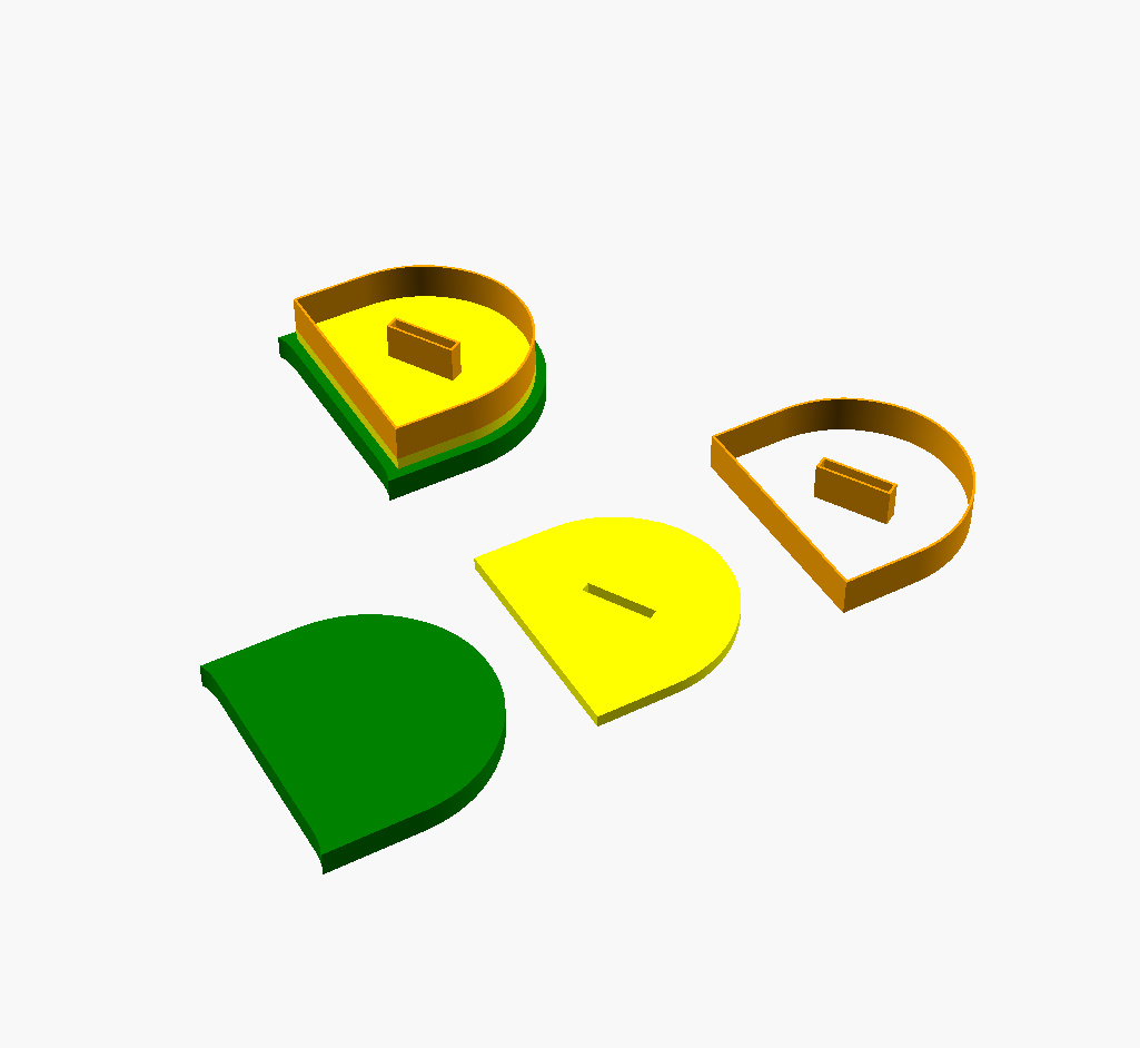
Initially, I thought of printing the back and casing in one step. But then I realized that that is not feasible. When doing that, I can’t put the LEDs in and solder the cables to connect them due to the height of the sides. So, these need to be two parts. But then I need to figure out how to keep the two parts together. The solution I used: create an inner wall that provides enough friction with the casing so that the backside sticks to the casing.
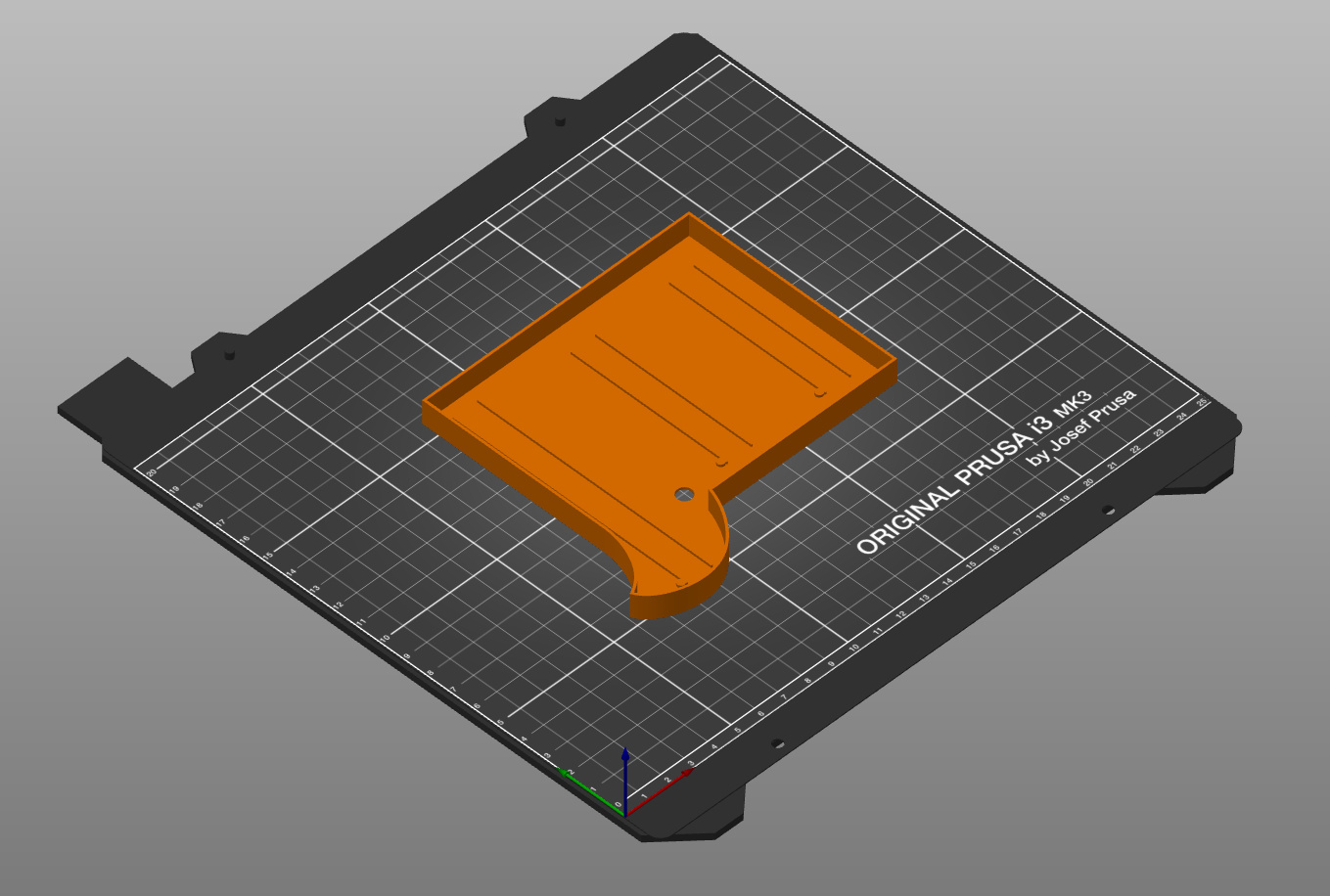
The picture shows the setup. On top of the backside (shown in green, but will be printed in black), we first put a layer (shown in yellow, but will be printed in white) to reflect the light of the LEDs. Then we add an inner wall (shown in orange, but also printed in white) to fit the back to the casing.
And this example shows how that is created:
// The backside
color("green")
    linear_extrude(height=BackThickness) {
        text(Text, CaseHeight, font=OuterFontName, valign="baseline");
        offset(r=1)
            text(Text, CaseHeight, font=InnerFontName, valign="baseline");
}

// The LED reflection layer
color("yellow")
    translate([0, 0, BackThickness])
        linear_extrude(height=LEDReflectionLayer)
            text(Text, CaseHeight, font=InnerFontName, valign="baseline");

// The sides to hold things together
color("orange")
    translate([0,0,BackThickness + LEDReflectionLayer])
        linear_extrude(height=BackInnerWallDepth)
            difference()
            {
                text(Text, CaseHeight, font=InnerFontName, valign="baseline");
                offset(delta=-(InnerWallThickness))
                    text(Text, CaseHeight, font=InnerFontName, valign="baseline");
            }
}
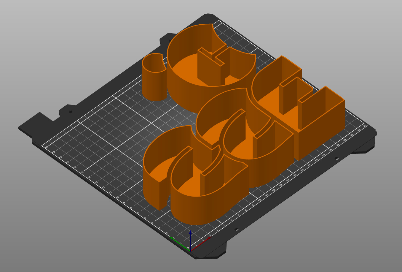
Placing the LEDs
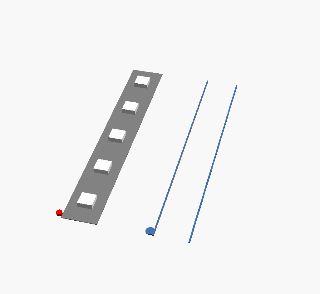
Once I got the backside of the sign designed, I printed it on a piece of paper and put some physical LEDs on it. Based on that, I guessed that I would need about 150+ LEDs for the whole sign. I could just work out the placement of the LEDs on paper and once the backside is printed, use that as a reference. However, we need to make sure that all the LEDs “point in the right direction” to correctly connect them.
To prevent that something could go wrong, I decided to embed the placement of the LEDs in the design of the backside.
The LED.scad file holds several modules to help with that during design/preview time.
That allowed me to find out where to place the strips, how many LEDs should go there and what the angle of the strip should be placed at.
And once the design is being rendered, it will add 2 lines and a little dot on the backside for reference. The lines are just wide enough to put the LED strip in between and the dot marks the “data in” side of the LEDs.
The picture shows the design time (left) view and the result (right) as printed on the backside.
Using the LED modules, I created an array of LED placement data per character that looks like this:
Letter1LED = [ [2, 87, 4, 50], [2, 53, 24, 120], [2, 38, 62, 270], [1, 48, 85, 270] ];
This character has 4 individual LED strips. The first value of an individual LED strip defines the number of LEDs, followed by the x, y coordinates and the angle of the strip. By looping through these values, it is a straightforward process to put the lines onto the backside.
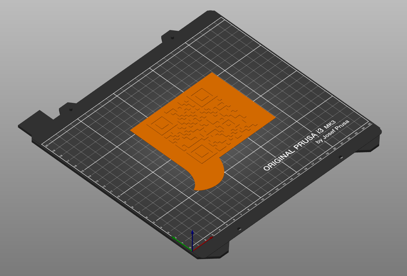
The QR-code
Initially, I had no idea what to do with the front of the electronics box, until I had to scan a QR code on a package. Problem solved: let’s put a QR code on the front holding the address of the website. A bit of browsing brought me to the QR Code generator for OpenSCAD. That went much smoother than expected 😊
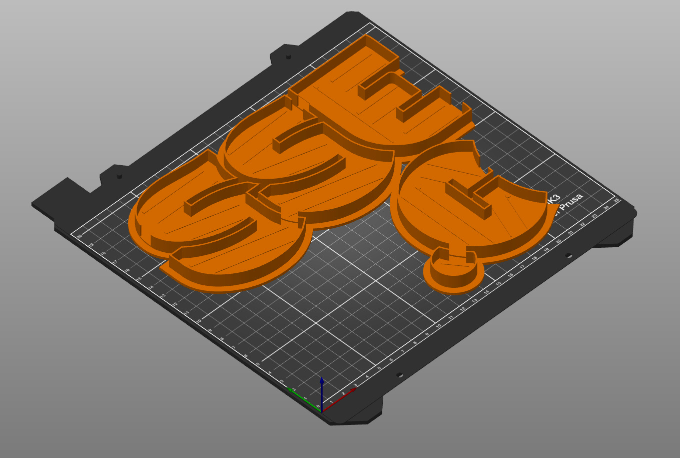
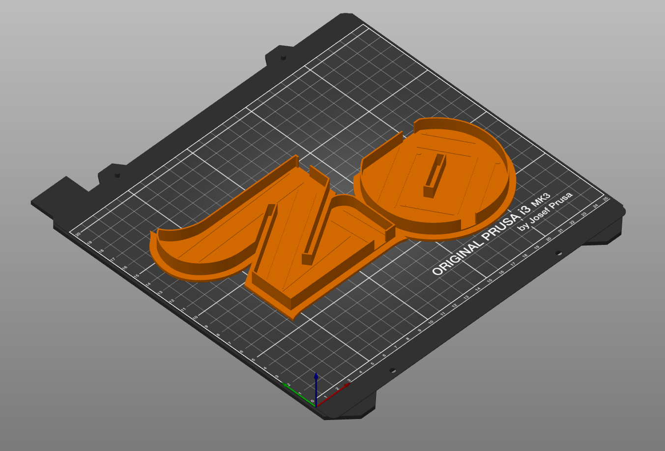
Rendering
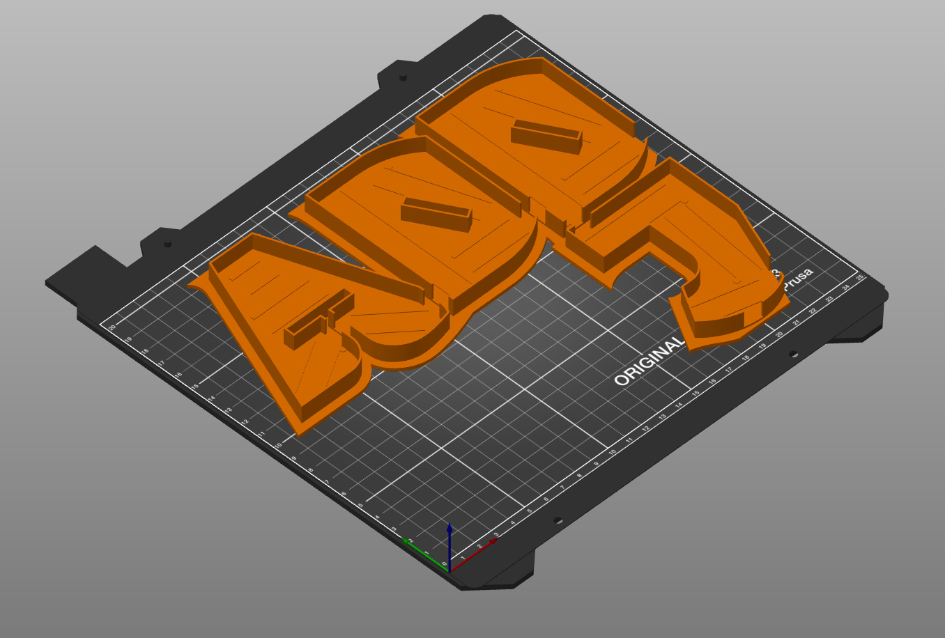
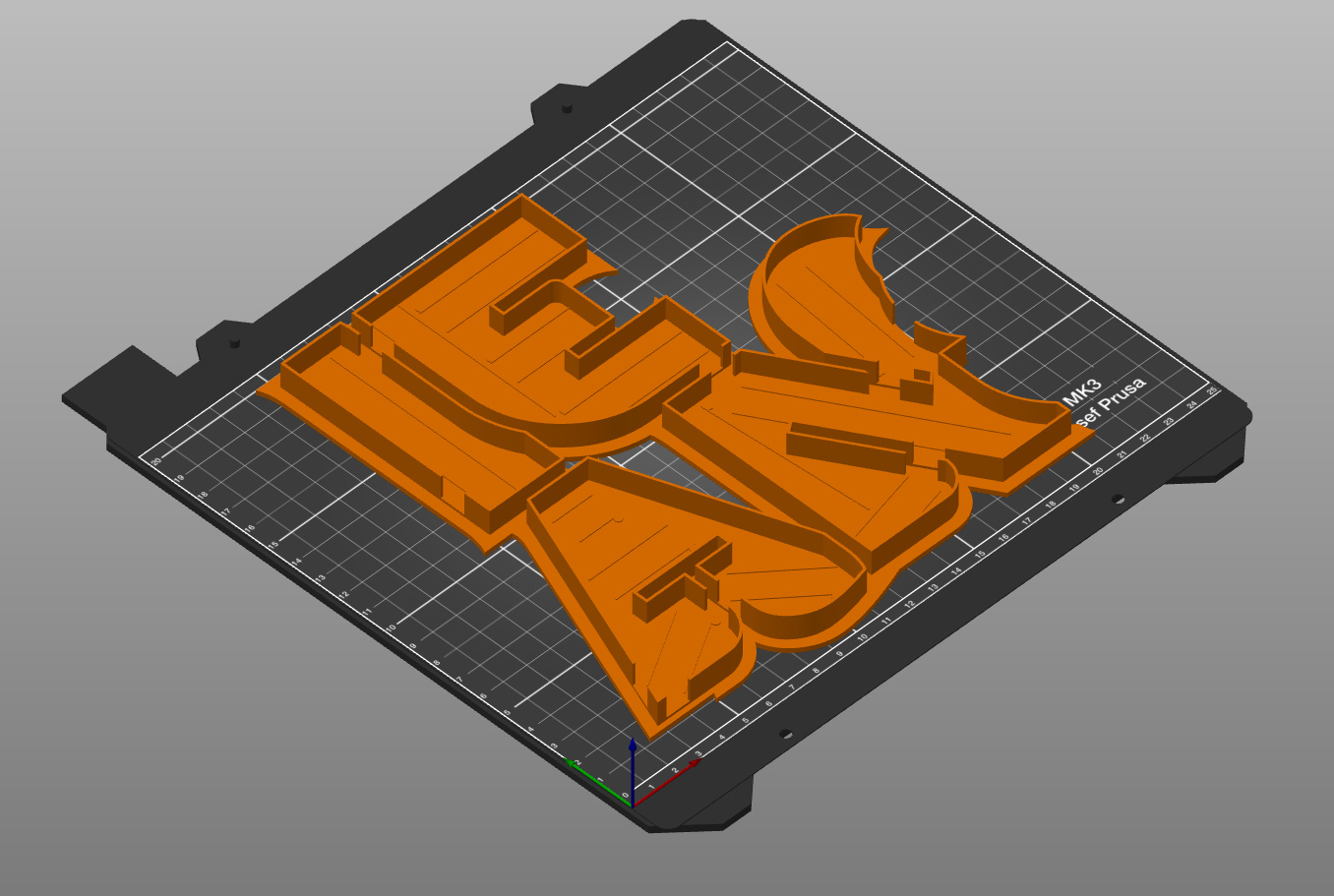
The name sign is too big to print in one go on my 3D printer.
It needs to be broken up in pieces.
Since there are no straight lines in the design where I can cut up the sign, I had to do it on the border of the individual characters.
This was a simple step in the design; by calculating a difference() on the parts.
Then it was time to start the high-quality render process and generate the .stl or .3mf files that I would need to print the parts.
To get the best quality arcs, we can set some OpenSCAD variables: $fa and $fs.
The lower the value of these, the higher the quality.
During the design process, I regularly rendered the sign with these variables set to 0.01. But suddenly that resulted in lots of error messages. I must have made a change that touched an OpenSCAD threshold. I got scared when I started to search for the error message… I was not the first one that ran into the problem and the general feedback from the public: you can’t trust OpenSCAD. Great… I just finished the design.
Somebody suggested to play with the values of the 2 variables and that is what I did. Eventually, I found out that using 0.2 would allow me to render all the parts and I could not see a real difference compared to the 0.01 I used before. Pfew…
Prusa advises to use .3mf files instead of .stl files if possible.
So, that is what I did.
But then I ran into problems with PrusaSlicer.
Some of the files would load correctly in PrusaSlicer, but when I sliced them, the result was missing parts of the objects…
I exported the same objects from OpenSCAD in an .stl file and had no issues at all.
And there they are; all the parts that need to be printed.


It was a nice journey to get here. I learned a lot about OpenSCAD and how to design a 3D object. There may be smarter ways of doing it, but I was not looking for the fastest/best way of doing this: this was to learn how to design something from the ground up.
By now, I have printed all the parts and the next article will be about the printing and assembly of the sign.
Want to respond to this post?
Look me up on GitHub,
 Facebook or
 LinkedIn.
Tags
- 3D 9
- Air Safari 19
- Australia 67
- BlackBerry 1
- Blue Sky Flying Adventures 33
- By Boat 4
- By Bus 2
- Dev Containers 3
- Domoticz 2
- Driving 31
- Facebook 1
- Flying 44
- Gallery 2 7
- Google Maps 4
- Hugo 1
- Jekyll 4
- Linux 3
- NextGEN Gallery 5
- Owning a plane 8
- Podman 3
- Red Centre Tour 19
- Singapore 3
- Tasmania 10
- USA 33
- WSL 2 4
- Walking 42
- WordPress 17